Put simply, the Q-factor of a crankset is the separation between the pedals. Typically road cranksets have smaller Q-factors then MTB cranksets.
In the days of square taper bottom brackets, the Q-factor of a particular set of cranks was dependent on the width of the bottom bracket. Narrow bottom brackets meant narrower Q-factors with the same cranks. For example, the old square taper FC-M750 combined with a 68-110mm UN72 bottom bracket had a Q-factor 167.7mm. The old XTR M952 cranks with the M952 bottom bracket in 112.5mm had an even narrower 163mm Q-factor.
The Shimano 'Hollowtech II' cranks changed all that because the crank spindle was now a fixed part of the chainring side crankarm. As a cost saving measure, the different bottom bracket shell widths and frame chainlines was accomodated, not by changing spindles as in the past, but by making the Q-factor seriously big and then using up to 3 spacers to get the chainline and fit correct. One size fits all.
This little DIY guide is about how you can go about reducing the Q-factor if your frame / physiology doesn't need the Q-factor that the stock Hollowtech cranks come with.
Assumptions
Shrinking the Q-factor using this guide involves removing various numbers of spacers. This will only work if:
- your frame has enough clearance for the crankarms and chainrings; and
- your bottom bracket shell in the frame is 68mm (if its 73mm then you will only ever be using one spacer and so this is the maximum you can remove).
Stock Q-factor
175mm.
2.5mm reduction: Q-factor = 172.5mm
This basically involves removing one of the spacers (each spacer is 2.5mm wide).
Removing the spacer is a piece of cake but there is a spacer between the bearing cups which protects the crank spindle and bearings from dirt/water that typically comes down the seat tube:
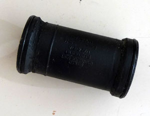
This spacer has ridges inboard of the o-rings that provide 'stops' when inserting into the bearing cups. These ridges need to be removed if you want to continue to use the spacer with a narrower Q-factor (unless you ride in a dustless desert, I'd highly recommend keeping the spacer otherwise the life of your bearings will be extremely short). The picture above shows what the internal spacer looks like after the 'stops' are removed.
I machined the ridges off using a lathe but you could easily remove them with a dremel or even sandpaper. The surface finish is not critical as its the o-rings that do all of the sealing.
Once the ridges are gone, the bearing cups can be as narrow as 66.2mm apart without any additional modification to the internal spacer. It really seems as if Shimano were keeping their options open with this design so there's less work for us tweakers to do.
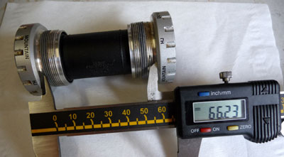
5mm reduction: Q-factor = 170mm
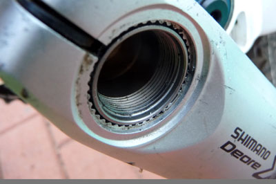
5mm reduction = remove 2 spacers. To do this you will need to machine the inside of the left crankarm so that it can fit further onto the crank spindle. You only need to remove about 2mm from the splines to get this to work. An appropriately adjusted fly cutter on the mill makes light work of this, but you could easily do the same thing with a little end-mill in your dremel:
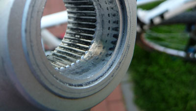
Note: although you're removing some of the spline engagement surface I don't think anything is being made weaker because with three spacers being used the axle actually finishes inside the left crank arm, so it does not fully engage with the full depth of splines.
Here's what things look like with a spacer removed from either side on my Anthem X (this was a test fit so the left crankarm isn't tightened right up against the left side bearing):
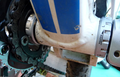
Here's where the crank spindle/axle ends up with 2 x 2.5mm spacers removed:
7.5mm reduction: Q-factor = 167.5mm
I have not gone down this path yet as I wanted to test the effect of the 5mm reduction first and the steps to go beyond 5mm require a significant amount of additional work.
To remove the third spacer you will need to shorten the axle by an almost equivalent (2.5mm amount). Machining off the end of the axle should be a piece of cake, although I'm not sure what the hardness of the steel used is.
The big job will be extending the splines on the axle. I suspect that they'll need to be ground in and hopefully the number required will be something sensible on the dividing head.
The other way to go would be to remove more of the splines within the left crank-arm but I'm concerned that this could result in the splines stripping under power.
10mm reduction: Q-factor = 165mm
The whole hog! To keep the cranks symmetrical about the bottom bracket then as well as removing the third 2.5 spacer from the drive side, the inner edge of the left hand crank should also be machined down 2.5mm.
So basically, if I was going to bother with extending the splines for the 7.5mm mod, then I'd extend them by a total of 5mm while I was at it. Then shorten the axle by 5mm and machine off 2.5mm of material on the left crank arm inner face. A relief would also need to be cut to hold the left crank arm bearing seal.
The full royale treatment would also involve cutting the inner axle bearing preload bolt thread 3mm deeper to ensure that you could still use the preload bolt properly.